Collimation Viewer is a real-time display that provides an intuitive guide to the corrections necessary to achieve perfect collimation. This tool uses the same calculation as the Curvature Map display, but shows the result in a form more suitable to real-time collimation:
Collimation Viewer can be started in two different ways:
Collimation viewer shows the three-screw, tip-tilt collimation arrangement that is commonly used on SCT's, RC's, Newtonians, and other styles of telescopes.
IMPORTANT: In order to use this tool effectively, CCD Inspector needs to be configured to know how the actual position of the collimation knobs and the position of the camera chip relative to the top of the telescope tube (OTA).
Here are the necessary configuration steps to start using the Collimation Viewer:
1. First, note that the top of the collimation viewer must always correspond
to the top of the OTA
2. When looking at an SCT from the front, the three knobs, labeled A,B, and C
need to be aligned to the top of the Collimation Viewer in the same way the
physical knobs are aligned to the top of the OTA. To align the display knobs,
click the left mouse button on one of them, and drag to rotate to the desired
position. Note that the labels A, B, and C are not important, and are used just
to make it easier to identify which button is being selected. Whether A, B, or C
is aligned with the top side in the above image does not matter, as long as one
of the knobs is located in this position.
3. The camera outline rectangle also needs to be rotated to the correct position
of the chip relative to the top of the telescope. To rotate the camera outline,
click on it with the right mouse button, and drag to rotate to the appropriate
position.
Important: CCD Inspector picks the most appropriate collimation knob to rotate. In order not to loosen the secondary mirror completely, avoid repeatedly turning any one knob in the counter-clock-wise direction.
With version 1.1.1, CCD Inspector will only recommend turning two out of the three knobs. This is done to prevent the complete loosening of the secondary that may result in damage to the telescope.
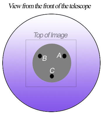
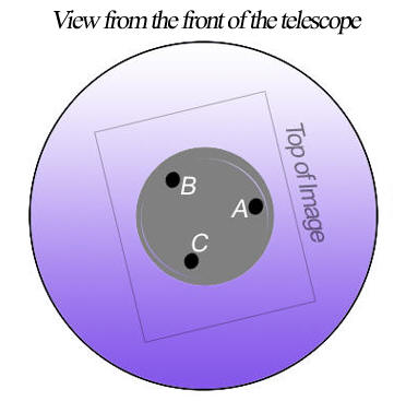
To collimate an SCT, start by looking at it from the front of the telescope towards the back. In the middle of the corrector, you'll find a the secondary mirror with three collimation screws or knobs.
The image below shows a schematic view of the front of the secondary mirror with collimation screws represented by circles A, B, and C (note that the actual labels are not important. They are there to make it easier to identify a knob on the telescope. If convenient, you can even add a sticker next to each of the knobs to label them with the corresponding letter. This will make it easier to identify which knob to turn when the telescope is rotated or when you are facing it from an difficult angle):
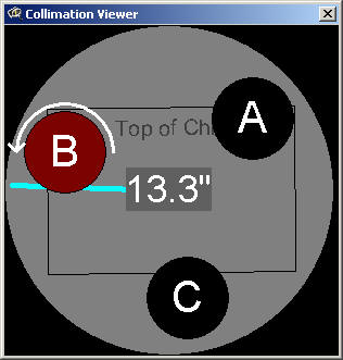
If your camera is positioned horizontally, as shown by the square, on the back focuser of the SCT, the top of the image will coincide with the top of the OTA and the top of the secondary mirror. To match the knobs to their position on the SCT , click and drag any of the A/B/C collimation knobs in the Collimation Viewer to rotate them to align with the top of image. The right image shows the correct position of the knob display for this SCT.
IMPORTANT: SBIG cameras have the CCD chip positioned in a way that makes the square part of the camera (the one with all the connector jacks) correspond to the top of the chip. In other words, if the camera is set up on the OTA so that the cables are hanging down from the camera, the top of the chip will be closer to the bottom of the OTA. The following photograph shows the camera position that makes the top of the captured CCD image align with the top direction in the photograph. This is the view from the front of the telescope towards the camera:
The following diagram was borrowed from a SBIG camera manual and represents the correct camera alignment at the back of the telescope to ensure that the top of the image corresponds to the top of the secondary mirror and the collimation knobs display:
In the following example, the first diagram shows that the camera is rotated counter-clock-wise by a 45º angle:
The picture in the middle shows what this means to the top of the image alignment as viewed from the front of the telescope. The diagram on the right shows the correct rotation of the Collimation Viewer knob display to match the top of the OTA, and the correct rotation of the camera/image outline to match the position of the camera relative to the OTA. This may be a little confusing, so let's follow this one step at a time:
1. The the image top is to the top left when looking at the back of the
telescope, as depicted in the first diagram.
2. When looking at the front of the telescope, as in the second diagram, the top
of the image now corresponds to the top right direction
3. There is a collimation knob on the telescope (labeled A) that corresponds
roughly to the right side of the OTA when viewed from the front. Therefore, the correct rotation of the Collimation Viewer
will have a knob (also labeled A for convenience) aligned with the top of the
collimation viewer.
Needless to say, the geometry can become complicated To simplify the process, you may want to try to always align the top of the image with the top of the OTA, as shown below:
In this case, the top of the image will always correspond to the top of the secondary, the top of the OTA, and the top of the collimation viewer display.
The same type of alignment procedure applies to an RC, MCT, or a Newtonian, although Newtonian may require a little experimentation to determine which knob corresponds to the top of the image, since the camera is positioned at a 90 degree angle to the primary. For the RC or Newtonian, simply imagine the Collimation Viewer knob display to show the back of the primary, with the three knobs controlling the tip-tilt of the primary mirror.
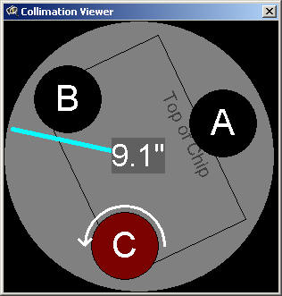
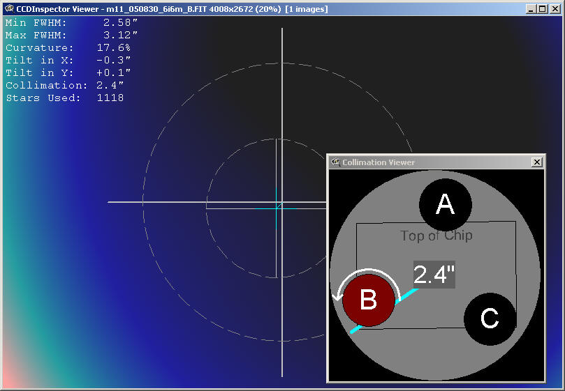
Once properly aligned, the Collimation Viewer will show the recommended collimation adjustment automatically, as soon as a new image is downloaded from the camera using your configured image acquisition software. The adjustments will show the knob to turn, and the direction to turn it.
The display shows:
The magnitude of the collimation error in the center of the display
The direction of the collimation error shown by a line from the center of the viewer display. The line only shows the direction of the error, not the error magnitude.
Recommended knob adjustment and adjustment direction, shown by highlighting the knob in red, and by drawing an arrow indicating the direction to turn the knob.
Number of stars detected in the image (shown in the title of the Collimation Viewer window). The same recommendations apply to the Collimation Viewer as do for the Curvature Map Viewer: 50 stars is a minimum, 100+ stars is recommended for a more accurate collimation computation, and proper star sampling is required.
Knob direction adjustment: the default setting for Collimation Viewer is to assume that turning each of the knobs clock-wise brings the mirror surface closer to the knob being turned. This is true for most commercial SCT's, RC's, and Newtonians.
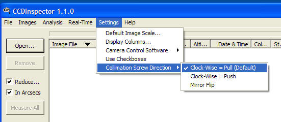
If your collimation mechanism works in the opposite direction (some focusers and refractor objective cells are designed this way), then you can tell CCDInspector to reverse the recommended direction by changing the Collimation Screw Direction setting from the main Settings Menu:
The default setting is Clock-Wise = Pull, meaning turning any of
the knobs clock-wise, pulls the mirror towards the knob, while
counter-clock-wise rotation pushes the mirror away. To reverse this, first close
the Collimation Viewer, click on the Clock-Wise = Push menu
option, and then start the Collimation Viewer again.
The Mirror Flip option is provided for those occasions when there is either an extra mirror or one less mirror in the light path to the camera. For example, a configuration that uses a diagonal or an AO-7 type-device which uses an internal mirror, mounted on an SCT, will contain 3 mirrors (primary, secondary, and AO-7 or diagonal). Even number of mirrors cancel each other out, odd number of mirrors (1 or 3) produce a mirror reflection of the image, and therefore require the Mirror Flip option to be checked.
Note that the Collimation Viewer window can be sized to be better visible from a distance: simply click and drag on the bottom-right corner of the window to increase or decrease the display size.